Leonardo filled folios with water machines. Bell drew his transmitter in the notebook beside the result. The Wrights, Tesla, Kilby and Dyson didn’t draw pretty pictures of machines. They drew just enough geometry, arrows, numbers and notes to hold their current theory of how the thing works, and to see where it broke.
FOURTEEN SKETCHES, FOURTEEN QUESTIONS
Each historical drawing suggests one engineering question. The Napkin studies built from them use modern, clearly labelled assumptions; none of them claims to reconstruct the original machine.
LEONARDO DA VINCI · c. 1480–1482 · MANUSCRIPT
Water-raising machines
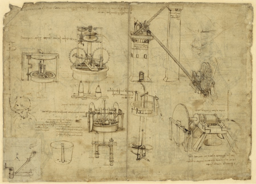
Codex Atlanticus, folio 1069r. Pen, ink and wash studies of water-raising mechanisms, screw forms and a siphon bucket. This sheet records several mechanisms rather than one finished machine.
The question: How much shaft power lifts a chosen water flow?
The lesson: A mechanism drawing can become a power budget before its gears become detailed geometry.
SOURCE: BIBLIOTECA AMBROSIANA ↗
ALEXANDER GRAHAM BELL · 10 March 1876 · NOTEBOOK
Liquid transmitter
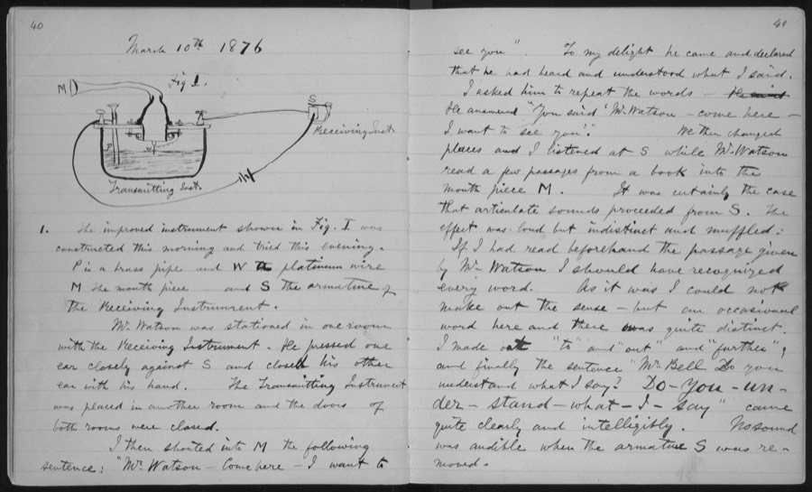
Laboratory notebook, pages 40–41, associated with the intelligible transmission experiment. This is an experimental record with an apparatus drawing, rather than a patent sheet.
The question: How large is a static current change from a resistance perturbation?
The lesson: Preserve the measured observation alongside the apparatus. A DC resistance model isolates one link in the sound-to-signal chain.
SOURCE: LIBRARY OF CONGRESS, MANUSCRIPT DIVISION ↗
BOULTON & WATT / R. H. THURSTON · 1878 · 1784 design · PUBLISHED ILLUSTRATION
Separate-condenser engine
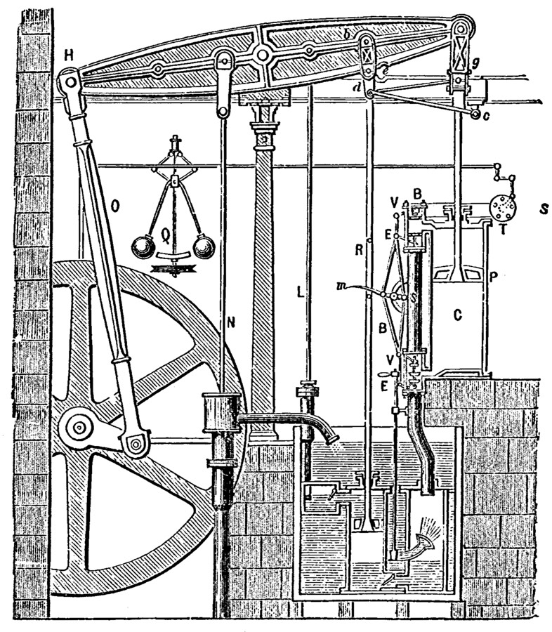
Thurston’s 1878 illustration depicts a Boulton & Watt engine design from 1784. It shows cylinder, valves, beam linkage, pumps and governor. It is a retrospective illustration, not Watt’s original condenser sketch.
The question: What shaft power follows from an assumed mean effective pressure?
The lesson: Separate the pressure-to-work calculation from the thermal explanation. The engine layout alone cannot supply its operating pressure.
SOURCE: R. H. THURSTON, 1878 ↗
THOMAS A. EDISON · 27 January 1880 · PATENT DRAWING
Carbon-filament lamp
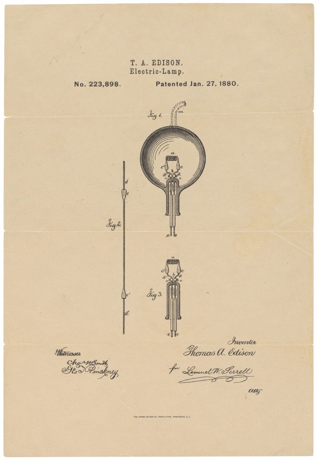
US223898, Electric Lamp: a carbon filament, sealed evacuated enclosure and electrical leads. The patent combines these elements; it is not evidence that electric light began with this disclosure.
The question: What current and power does an assumed hot filament draw?
The lesson: A lamp is an electrical, thermal and materials system. Start with the supply and hot resistance, then identify the missing thermal evidence.
SOURCE: U.S. NATIONAL ARCHIVES ↗
NIKOLA TESLA · 1 May 1888 · PATENT DRAWING
Rotating-field motor
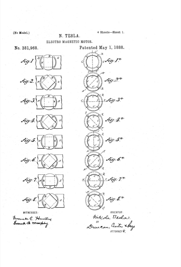
US381968, Electro-Magnetic Motor, sheet 1. Electrical phase arrangements produce progression of magnetic poles and rotor motion; the sheet combines circuits with physical layout.
The question: How do assumed slip and mechanical output set shaft speed and torque?
The lesson: Translate field motion into synchronous speed. Treat slip as a measured or assumed input until a richer motor model is available.
SOURCE: NIKOLA TESLA · US381968 ↗
ORVILLE & WILBUR WRIGHT · 22 May 1906 · PATENT DRAWING
Wing-warping aircraft
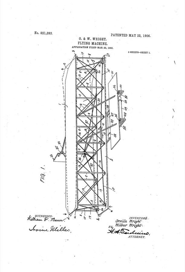
US821393, Flying-Machine, sheet 1. Filed in 1903, it emphasizes equilibrium, wing deformation and coordinated control. The visible artifact shows a glider/control architecture, not the powered 1903 Flyer.
The question: What airspeed gives enough idealized lift for an assumed mass?
The lesson: Lift sizing gives a useful first gate, but a passing lift check says nothing about whether wing warping restores equilibrium.
SOURCE: ORVILLE & WILBUR WRIGHT · US821393 ↗
ROBERT H. GODDARD · 7 July 1914 · PATENT DRAWING
Multistage rocket
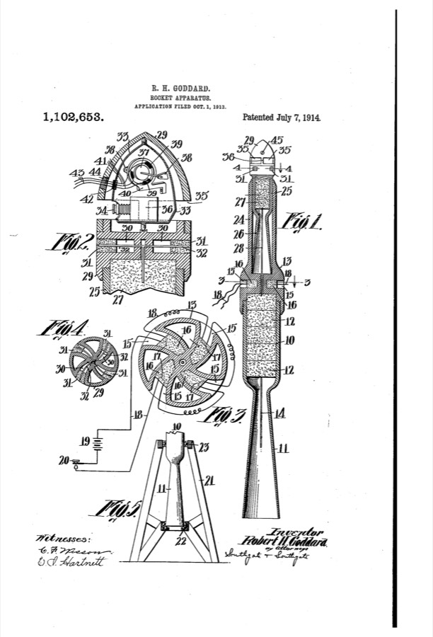
US1102653, Rocket Apparatus, sheet 1. The disclosure describes solid explosive disks, a primary rocket and an auxiliary rocket. This is staged solid-charge apparatus, distinct from Goddard’s 1926 liquid-fuel flight.
The question: What ideal velocity budget results from two assumed stage mass ratios?
The lesson: A staged system needs an explicit mass-accounting boundary. An ideal velocity budget is one question; successful staging is another.
SOURCE: ROBERT H. GODDARD · US1102653 ↗
FRANK WHITTLE · 8 August 1939 · PATENT DRAWING
Turbojet flow path
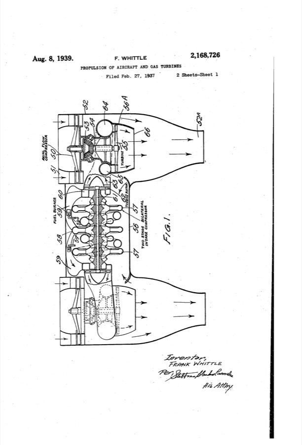
US2168726, Propulsion of Aircraft and Gas Turbines, sheet 1. The cross-section links compression, combustion, turbine drive and propulsive discharge. This displayed US patent is dated 1939, not the earlier British filing.
The question: What momentum thrust follows from assumed inlet and exit conditions?
The lesson: Flow components must balance momentum and energy as well as fit. Begin with the exit conditions, then ask where those conditions come from.
SOURCE: FRANK WHITTLE · US2168726 ↗
HEDY LAMARR & GEORGE ANTHEIL · 11 August 1942 · PATENT DRAWING
Synchronized frequency hopping
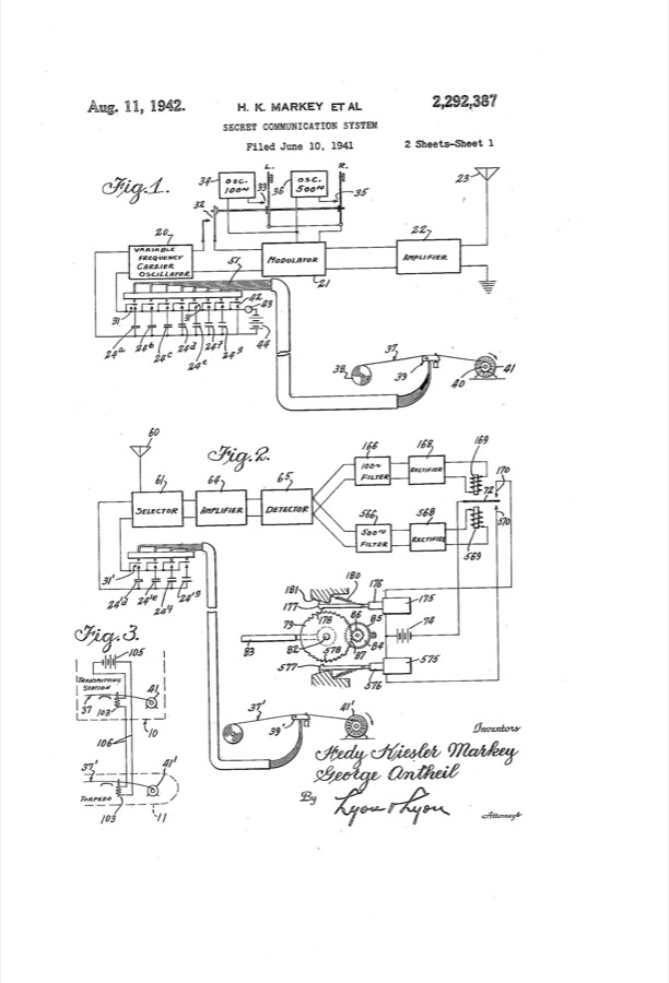
US2292387, Secret Communication System, credits Hedy Kiesler Markey and George Antheil. Matched record mechanisms coordinate transmitter and receiver frequency changes for remote control. This is not a modern Wi-Fi implementation.
The question: How much time remains after retuning and synchronization allowances?
The lesson: Timing agreement is an engineering requirement. Budget dwell, retuning and uncertainty before claiming a usable communication channel.
SOURCE: HEDY KIESLER MARKEY & GEORGE ANTHEIL · US2292387 ↗
R. BUCKMINSTER FULLER · 29 June 1954 · PATENT DRAWING
Geodesic structure
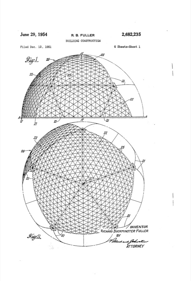
US2682235, Building Construction, sheet 1. Repeated structural members organize an approximately spherical enclosure. The drawing supports a geometric construction rule, not a universal priority claim for geodesic geometry.
The question: What axial stress follows for one idealized loaded strut?
The lesson: Local member geometry can build a global shell; local stress cannot by itself establish global stability.
SOURCE: R. BUCKMINSTER FULLER · US2682235 ↗
GEORGE DE MESTRAL · 13 September 1955 · PATENT DRAWING
Hook-and-loop fastening
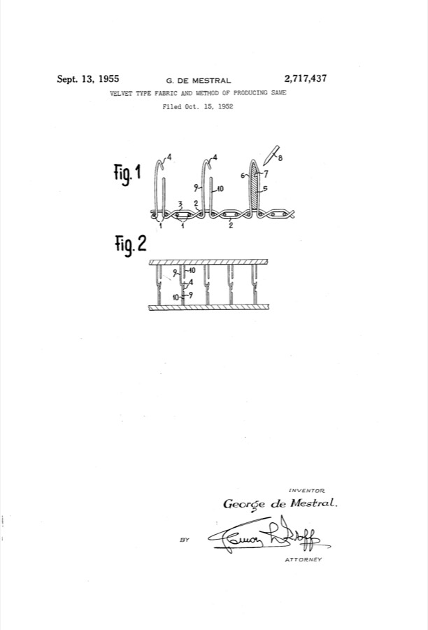
US2717437, Velvet Type Fabric and Method of Producing Same. The disclosure describes manufactured fabric and engaging hook formation. “Hook-and-loop” names the mechanism; VELCRO is a trademark.
The question: How large a bonded engagement area carries an assumed shear load?
The lesson: Turn a material mechanism into an empirical load-per-area rule. The measurement conditions matter as much as the chosen area.
SOURCE: GEORGE DE MESTRAL · US2717437 ↗
JACK S. KILBY · 23 June 1964 · PATENT DRAWING
Miniaturized circuit
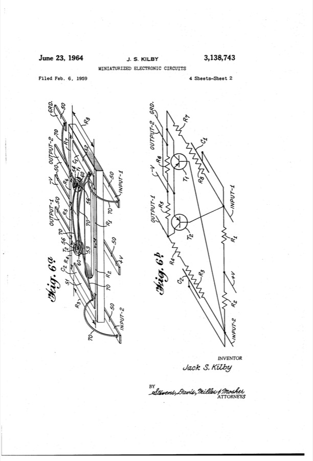
US3138743, Miniaturized Electronic Circuits, sheet 2, figures 6a/6b. Physical layout and equivalent circuit appear together. This is a patent substitute for the 1958 notebook; the key view was published sideways.
The question: How does assumed lumped parasitic capacitance limit a simple RC response?
The lesson: Keep physical arrangement and circuit topology distinct. A generic RC proxy tests one miniaturization tradeoff without pretending to reconstruct this circuit.
SOURCE: JACK S. KILBY · US3138743 ↗
DOUGLAS C. ENGELBART · 17 November 1970 · PATENT DRAWING
X–Y position indicator
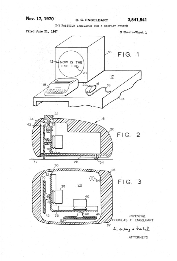
US3541541, X-Y Position Indicator for a Display System, sheet 1. Orthogonal wheels turn hand motion into display-position signals. This artifact is the patent drawing, not an image from the 1968 demonstration.
The question: What surface displacement corresponds to one wheel-encoder count?
The lesson: Resolve motion into independent coordinates, then ask how wheel geometry sets the smallest displacement you can report.
SOURCE: DOUGLAS C. ENGELBART · US3541541 ↗
JAMES DYSON · 10 June 1986 · PATENT DRAWING
Cyclonic vacuum cleaner
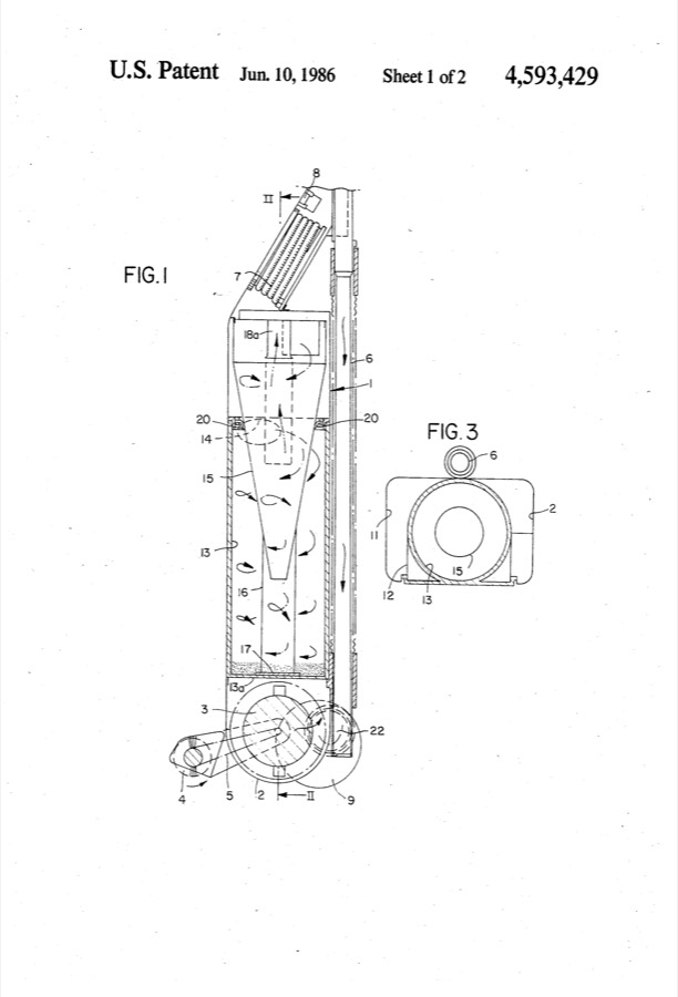
US4593429, Vacuum Cleaning Appliance, sheet 1. Airflow links the cleaning head, cyclone arrangements, dust collection and cleaner body. The drawing does not establish a particular number of prototypes.
The question: How much fan shaft power supports an assumed flow and pressure drop?
The lesson: Follow the airflow and its pressure losses. A fan-power budget is useful even while particle separation needs measurement or a richer model.
SOURCE: JAMES DYSON · US4593429 ↗