HISTORICAL DRAWING · 1964 (filed 1959)
Miniaturized circuit
How does assumed lumped parasitic capacitance limit a simple RC response?
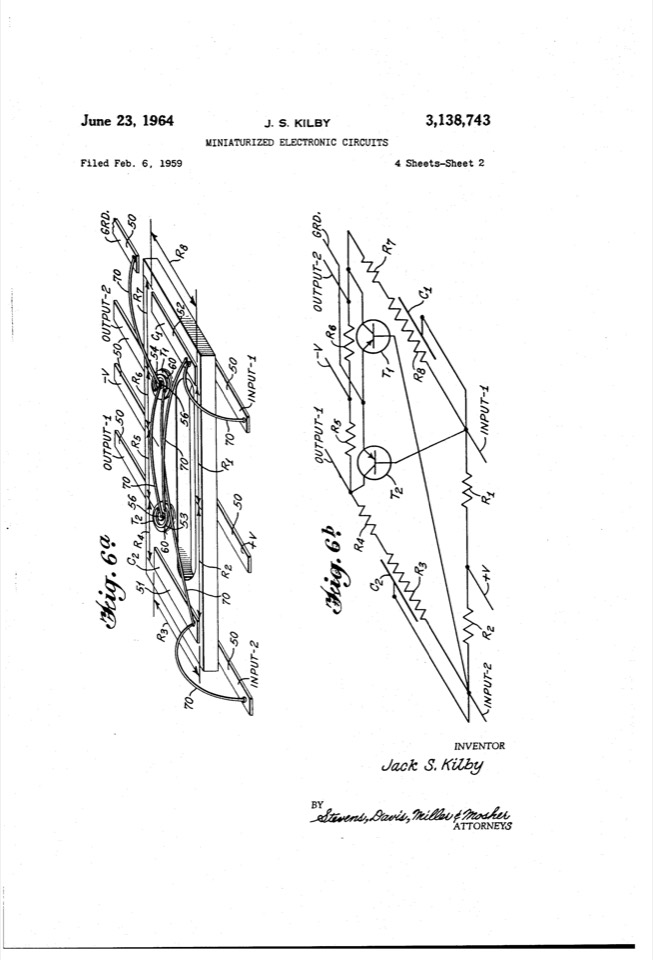
A contemporary sketch model
Every number below is a modern illustrative assumption. The historical drawing supplies a question; the source model is an exercise in reasoning about it.
resistance = 1000 ohm "Illustrative circuit resistance"
capacitance = 20 pF in 5..100 "Assumed lumped capacitance"
timeConstant := resistance*capacitance [ns]
riseTime := 2.2*timeConstant [ns]
frequencyLimit := 1/(2*pi*timeConstant) [MHz]
check edge: riseTime <= 100 ns
check bandwidth: frequencyLimit >= 5 MHz
sweep Parasitic: capacitance = 5, 20, 100 pF
Model limits
A generic one-pole proxy motivated by miniaturization, not the patent circuit reconstructed or simulated. No SPICE or transistor model.
Explore it with your agent
Create a Study, inspect the installed capabilities, and use this source as a starting point. Ask the agent to explain the equations and assumptions, then replace illustrative inputs with measured evidence for your own design.
This example includes a scalar sweep. Use napkin_sketch to add the model and napkin_run to inspect the sweep; the source editor’s scalar comparison view is for simple scenarios.